Reliable Power for a Better Cutting Experience
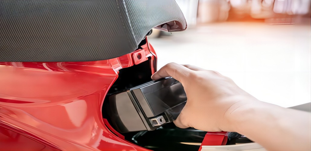
A smooth mowing experience starts with a battery that delivers consistent and dependable power. Traditional batteries often struggle with slow starts, reduced performance, and frequent maintenance, especially after long periods of storage. A high-quality U1 LFP Battery Replacement provides stable energy output to help your mower start quickly and run efficiently, making every yard maintenance task easier and more convenient.
Longer Runtime Means Less Time on Battery Issues
Nobody wants to stop halfway through mowing because of unexpected power loss. Modern lawn mower batteries are designed to offer improved energy efficiency and longer operating time, allowing you to complete more work with fewer interruptions. Whether you are maintaining a small residential yard or a larger outdoor space, choosing the right battery helps maximize productivity and reduces the hassle of frequent recharging or replacement.
Built for Seasonal Use and Long-Term Performance
Lawn equipment often sits unused during colder months, which can put traditional batteries under stress. Advanced battery technology helps minimize power loss during storage and provides reliable performance when the mowing season begins again. A durable Group U1 Lawn Mower Battery is designed to handle repeated charging cycles while maintaining strong starting power, helping extend the overall lifespan of your lawn equipment.
Low Maintenance Solution for Busy Homeowners
Battery maintenance can be time-consuming, especially with older lead-acid models that require regular checks and care. Newer lawn mower batteries offer a more user-friendly experience with fewer maintenance requirements. With improved internal design and dependable construction, they allow homeowners to focus more on lawn care and less on battery upkeep.
Enhanced Starting Power in Different Conditions
Weather conditions can affect how quickly your lawn mower starts. From early spring mornings to hot summer afternoons, a reliable battery needs to perform consistently in changing environments. A powerful starting battery provides the energy needed to turn over your mower engine efficiently, helping you avoid frustrating delays before getting your yard work done.
A Smarter Upgrade Compared with Traditional Batteries
Upgrading your mower battery is not just about replacing an old component—it is about improving the entire lawn care experience. Compared with conventional options, lithium-based solutions can offer advantages such as lighter weight, longer service life, faster charging capability, and better energy efficiency. For many users, switching to a modern Group U1 Lawn Mower Battery is a practical investment that delivers value over time.
Choose the Right Battery to Keep Your Lawn Looking Its Best
Your lawn mower depends on reliable power to deliver consistent results throughout the season. Selecting a battery that matches your equipment specifications ensures better performance, fewer interruptions, and greater convenience. Whether you are replacing an aging battery or upgrading your mower setup, choosing the right solution can help you spend less time dealing with equipment problems and more time enjoying a well-maintained yard.
...